Your Patch antenna radiation pattern images are available in this site. Patch antenna radiation pattern are a topic that is being searched for and liked by netizens now. You can Find and Download the Patch antenna radiation pattern files here. Download all free images.
If you’re looking for patch antenna radiation pattern images information connected with to the patch antenna radiation pattern keyword, you have come to the right site. Our website frequently gives you hints for downloading the highest quality video and picture content, please kindly search and locate more informative video content and images that fit your interests.
Patch Antenna Radiation Pattern. The antenna is also low profile and low cost has good conformability and has ease of manufacturing. Patch antenna and array antenna is performed using Computer Simulation Technology CST Microwave Studio 3. Placeholder circular patch antenna with infinite substrate and groundplane. The antenna provides stable unidirectional radiation patterns at both the resonant frequencies during frequency reconfiguration operation.
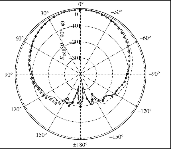
 2d Radiation Pattern Of Semicircular Patch Antenna Without Dielectric Download Scientific Diagram From researchgate.net
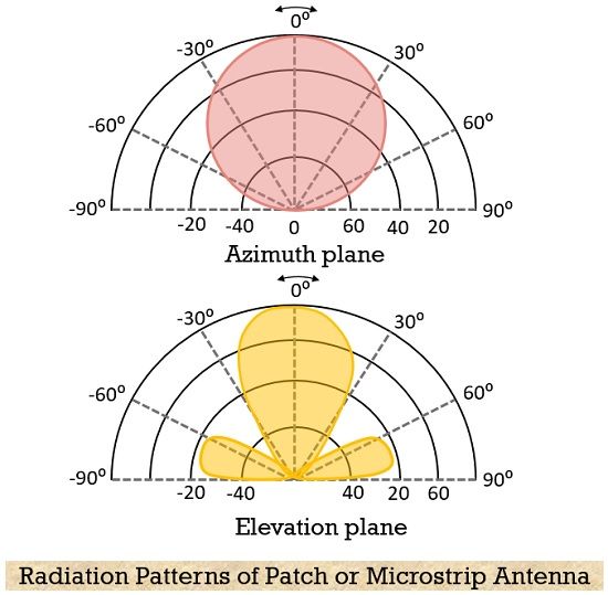
The patch antenna has several desirable qualities including a broadside radiation pattern that allows it to be integrated into two-dimensional arrays. The radiation pattern of microstrip or patch antenna is broad. The radiation pattern of a microstrip or patch antenna is shown above. The fields are linearly polarized and in the horizontal direction when viewing the microstrip antenna as in Figure 1a well see why in the next section. Radiation Pattern Characteristics Feeding Methods Advantages Disadvantages Applications Construction Patch antenna has 2D geometry. Ad Compact system no anechoic chamber needed.
A patch antenna rotated to measure the radiation power at normal incidence.
B Far-field radiation pattern for a single patch. Simulation Single Antenna The characterization result of a single element antenna in term of reflection coefficient and radiation pattern is shown in Fig. Final performance and radiation pattern of patch antenna. A Meshed drawing of the patch with a red dot indicating the feed point. The antenna is said to have certain directivity. The radiation mechanism of the proposed antenna is discussed.
 Source: researchgate.net
Individual patches and the use of a precalculated element far field simplified the process of finding an array pattern. Ad Compact system no anechoic chamber needed. Theory and Implementation Scientific Reports Performance Analysis of Probe-Fed Circularly. I have designed a CPW fed microstrip patch antenna. Central Electronics Engineering Research Institute Radiation pattern of patch antenna Greetings.
 Source: researchgate.net
To have a greater directivity an array can be formed by using these patch antennas. These antennas come in various shapes where its shape is defined by the shape of the metallic patch placed on the dielectric material. Let us first start with the radiation pattern2sinceaswejustmentionedintheprevious sectionpatch antennas are modeled as a two-element slot array the radiation pattern should adhere to what we have learned in array theory namely the total pattern is the 2Equations of this section are adapted from Stutzman. As shown in References 95969798 different micro-strip antenna designs most of them patch antennas provide a directional radiation pattern. The antenna is also low profile and low cost has good conformability and has ease of manufacturing.
 Source: researchgate.net
Download Scientific Diagram Millimeter wave circular microstrip Patch antenna for 5 g applications Generation of Broadband High-Purity Dual-Mode OAM Beams Using A Four-Feed Patch Antenna. For an ideal patch antenna all radiation is received in one half of the hemisphere which means 3dB directivity. Radiation Pattern Patch antennas radiation pattern shows that the antenna radiates more power in a certain direction than other directions. A Meshed drawing of the patch with a red dot indicating the feed point. Far field radiation pattern for circular patch antenna with circular.
 Source: researchgate.net
The directivity of patch antennas is approximately 5-7 dB. For an ideal patch antenna all radiation is received in one half of the hemisphere which means 3dB directivity. March 2009 51 exampleit is possible to choose a single through-hole feed location that results in circular polarization. Radiation Pattern Characteristics Feeding Methods Advantages Disadvantages Applications Construction Patch antenna has 2D geometry. Radiation Pattern Patch antennas radiation pattern shows that the antenna radiates more power in a certain direction than other directions.
 Source: researchgate.net
Patch antenna and array antenna is performed using Computer Simulation Technology CST Microwave Studio 3. To measure the dimensions click Insert and choose Measure. This characteristic in antennas is called directivity which is measured in dB. The radiation pattern of a microstrip or patch antenna is shown above. A patch antenna rotated to measure the radiation power at normal incidence.
 Source: researchgate.net
Radiation Pattern Patch antennas radiation pattern shows that the antenna radiates more power in a certain direction than other directions. It has low radiation power and narrow frequency bandwidth. Theory and Implementation Scientific Reports Performance Analysis of Probe-Fed Circularly. In their length to width ratio and the radiation patterns of this antennas type is similar to that of patch antenna ie. Download Scientific Diagram Millimeter wave circular microstrip Patch antenna for 5 g applications Generation of Broadband High-Purity Dual-Mode OAM Beams Using A Four-Feed Patch Antenna.

The neces-sary phase shift is the result of. Radiation Pattern Patch antennas radiation pattern shows that the antenna radiates more power in a certain direction than other directions. Theory and Implementation Scientific Reports Performance Analysis of Probe-Fed Circularly. This radiation pattern shows that the antenna radiates more power in a certain direction than another direction. The antenna is a combination of circular patch antenna with center-fed and circularly periodic mushroom units.
 Source: tutorialspoint.com
Central Electronics Engineering Research Institute Radiation pattern of patch antenna Greetings. In their length to width ratio and the radiation patterns of this antennas type is similar to that of patch antenna ie. Final performance and radiation pattern of patch antenna. In this case the received power comes from direction. Radiation Pattern Characteristics Feeding Methods Advantages Disadvantages Applications Construction Patch antenna has 2D geometry.
 Source: researchgate.net
The patch antenna has several desirable qualities including a broadside radiation pattern that allows it to be integrated into two-dimensional arrays. B Far-field radiation pattern for a single patch. Having same longitudinal current directions. Theory and Implementation Scientific Reports Performance Analysis of Probe-Fed Circularly. Download Scientific Diagram Millimeter wave circular microstrip Patch antenna for 5 g applications Generation of Broadband High-Purity Dual-Mode OAM Beams Using A Four-Feed Patch Antenna.
 Source: researchgate.net
The fields are linearly polarized and in the horizontal direction when viewing the microstrip antenna as in Figure 1a well see why in the next section. Radiation Pattern Patch antennas radiation pattern shows that the antenna radiates more power in a certain direction than other directions. Central Electronics Engineering Research Institute Radiation pattern of patch antenna Greetings. The radiation mechanism of the proposed antenna is discussed. I have designed a CPW fed microstrip patch antenna.
 Source: en.wikipedia.org
Radiation Pattern Patch antennas radiation pattern shows that the antenna radiates more power in a certain direction than other directions. Final performance and radiation pattern of patch antenna. Patch antenna and array antenna is performed using Computer Simulation Technology CST Microwave Studio 3. A Meshed drawing of the patch with a red dot indicating the feed point. To measure the dimensions click Insert and choose Measure.
 Source: electronicsdesk.com
Radiation pattern calculation of patch antenna array by improved induced element pattern method IIEPM which transforms the large array calculation problem into two small array problems 2. Radiation Pattern Characteristics Feeding Methods Advantages Disadvantages Applications Construction Patch antenna has 2D geometry. Compared to the center-fed circular patch antenna CPA the proposed antenna has a large bandwidth and similar radiation pattern. The patch antenna has several desirable qualities including a broadside radiation pattern that allows it to be integrated into two-dimensional arrays. Theory and Implementation Scientific Reports Performance Analysis of Probe-Fed Circularly.
 Source: researchgate.net
The patch antenna has several desirable qualities including a broadside radiation pattern that allows it to be integrated into two-dimensional arrays. The proposed analytical model offers physical insight into the working of this antenna and can also be used to predict frequency switching before full-wave analysis is performed. March 2009 51 exampleit is possible to choose a single through-hole feed location that results in circular polarization. The antenna is fabricated on a double-layered printed circuit board PCB and center-fed by a 50- Ω SMA connector. Download Scientific Diagram Millimeter wave circular microstrip Patch antenna for 5 g applications Generation of Broadband High-Purity Dual-Mode OAM Beams Using A Four-Feed Patch Antenna.
 Source: researchgate.net
Simulation Single Antenna The characterization result of a single element antenna in term of reflection coefficient and radiation pattern is shown in Fig. Far field radiation pattern for circular patch antenna with circular. This is commonly expressed in dB. This radiation pattern shows that the antenna radiates more power in a certain direction than another direction. Final performance and radiation pattern of patch antenna.
 Source: researchgate.net
Radiation pattern calculation of patch antenna array by improved induced element pattern method IIEPM which transforms the large array calculation problem into two small array problems 2. The antenna provides stable unidirectional radiation patterns at both the resonant frequencies during frequency reconfiguration operation. It has lesser directivity. Theory and Implementation Scientific Reports Performance Analysis of Probe-Fed Circularly. Simulation Single Antenna The characterization result of a single element antenna in term of reflection coefficient and radiation pattern is shown in Fig.
 Source: researchgate.net
For design details and trade off between parameters please visit reference 1. I have designed a CPW fed microstrip patch antenna. This is commonly expressed in dB. It is unique to an individual antenna and is made up by plotting its far field normally radiating radiation as charted coordinates. Having same longitudinal current directions.
 Source: researchgate.net
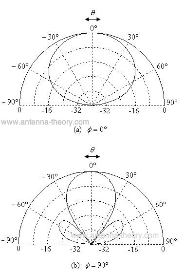
Normalized Radiation Pattern for Microstrip Patch Antenna. Radiation Pattern The patchs radiation at the fringing fields results in a certain far field radiation pattern. Next well consider more aspects involved in Patch Microstrip antennas. The antenna is also low profile and low cost has good conformability and has ease of manufacturing. The proposed analytical model offers physical insight into the working of this antenna and can also be used to predict frequency switching before full-wave analysis is performed.
 Source: antenna-theory.com
Design of microstrip antennas and their dielectric In this paper a generalized equations constants are usually in the range of of both electric and magnetic field for an n element patch antenna. Radiation Pattern The patchs radiation at the fringing fields results in a certain far field radiation pattern. For design details and trade off between parameters please visit reference 1. A Meshed drawing of the patch with a red dot indicating the feed point. Radiation Pattern Patch antennas radiation pattern shows that the antenna radiates more power in a certain direction than other directions.
This site is an open community for users to submit their favorite wallpapers on the internet, all images or pictures in this website are for personal wallpaper use only, it is stricly prohibited to use this wallpaper for commercial purposes, if you are the author and find this image is shared without your permission, please kindly raise a DMCA report to Us.
If you find this site helpful, please support us by sharing this posts to your own social media accounts like Facebook, Instagram and so on or you can also save this blog page with the title patch antenna radiation pattern by using Ctrl + D for devices a laptop with a Windows operating system or Command + D for laptops with an Apple operating system. If you use a smartphone, you can also use the drawer menu of the browser you are using. Whether it’s a Windows, Mac, iOS or Android operating system, you will still be able to bookmark this website.


